Projection and view
- Projection system and terms in projection
- classification of projection
- Parallel projection
- orthogonal
- Two view
- Three view
- Multi view
- Pictorial projection
- Oblique
- Cavalier
- Cabinet
- Perspective
- Axonometric
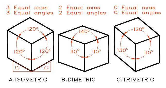
- Isometric projection
- Dimetric projection
- Trimetric projection
- Oblique
- orthogonal
- Angular projection
- Parallel projection
- TOP VIEW, FRONT VIEW, SIDE VIEW, left side VIEW , right side VIEW, bottom view, back view
- First Angle projection
- Second Angle projection
- Third Angle projection
- Fourth Angle projection
- Difference b/w First Angle projection and Third Angle projection
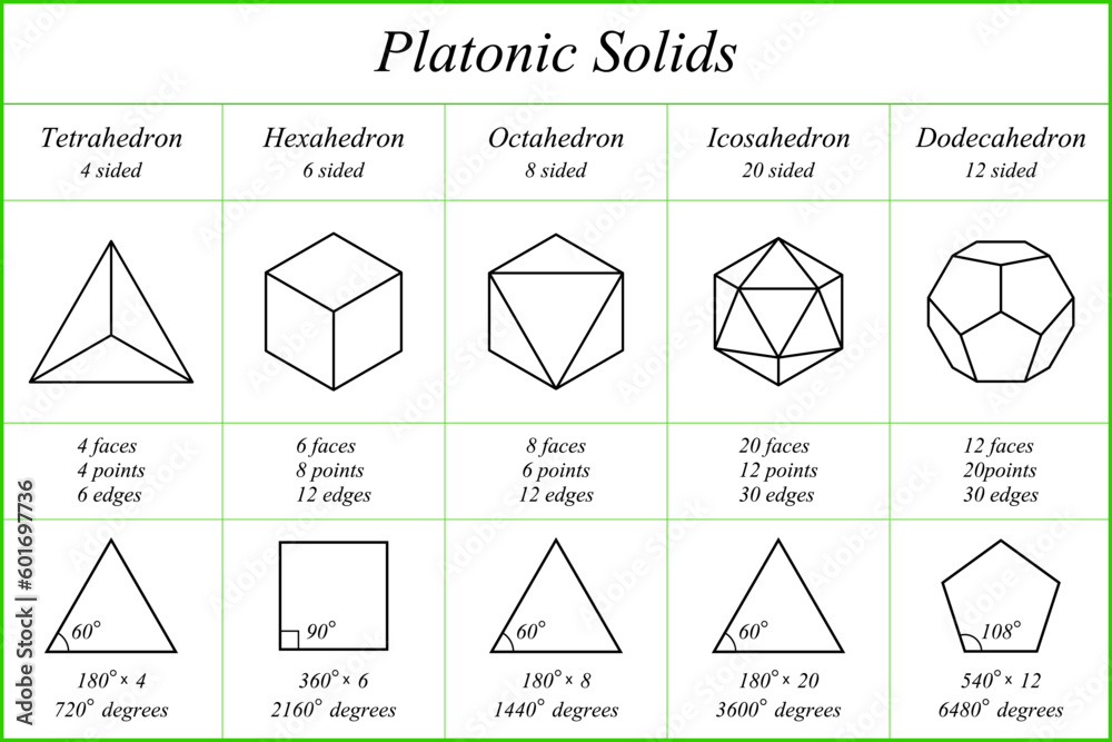
- tetrahedron
- hexahedron
- octahedron
- dodecahedron
- icosahedron
Parallel projection : Parallel projection is a method used to represent three-dimensional objects on a two-dimensional surface. It involves projecting lines of sight that remain parallel to each other throughout the process. This technique is particularly useful in technical and engineering drawings where precision is crucial, as it maintains the object’s dimensions and proportions accurately
- Lines of Projection: Remain parallel to each other and do not converge.
- Realism: Does not create a realistic view of depth as perspective projection does.
- Accuracy: Maintains accurate dimensions and proportions of the object.
- Applications – Parallel projection is widely used in engineering and architectural drawings for its ability to provide precise measurements and representations of objects
Types of Parallel Projection
Orthographic Projection:
- Definition: Involves projecting an object onto a series of perpendicular planes, typically resulting in multiview drawings such as front, top, and side views.
- Subtypes:
- Multiview Projection: Displays multiple views of an object, often including first-angle, second-angle, third-angle, and fourth-angle drawings.
- Axonometric Projection: Includes isometric, dimetric, and trimetric projections, which are used to represent objects in a three-dimensional manner without perspective.
- Pictorial projections : Pictorial projections in engineering drawing are used to represent three-dimensional objects on a two-dimensional plane, providing a more realistic view compared to orthographic projections.
- The main types of pictorial projections are:
- Oblique
- Cavalier
- Cabinet
- Perspective
- Axonometric
- Isometric projection
- Dimetric projection
- Trimetric projection
- Oblique
- Isometric Projection
- All three axes (X, Y, and Z) are inclined at 120° to each other or the angles between the axes are all the same.
- The lengths along each axis are equally foreshortened.
- It provides a clear view of the object’s shape and dimensions.
- Dimetric Projection
- Two axes are equal, while the third is at a different angle
- Two axes have the same level of foreshortening, while the third axis is different.
- It is less common but used when an object has two dominant dimensions.
- Trimetric Projection
- All three axes are at different angles
- All three axes have different foreshortening.
- It provides the most realistic view but is complex to construct.
- Oblique Projection
- Projectors are parallel but at an angle other than 90° to the picture plane.
- The front face is drawn true to size, while the depth is represented at an angle (typically 30°, 45°, or 60°).
- Two types:
- Cavalier Projection: Full depth is retained.
- Uses a 45° angle for the projection.
- Cabinet Projection: Depth is halved to reduce distortion.
- Uses a 30° angle for the projection, reducing the size of the object’s depth dimension.
- Cavalier Projection: Full depth is retained.

Difference Between Orthogonal and Oblique Projections
| Feature | Orthogonal Projection | Oblique Projection |
|---|---|---|
| Definition | A projection method where projection lines are perpendicular (90°) to the projection plane. | A projection method where projection lines are at an oblique (angled) direction to the projection plane. |
| Direction of Projection | Projectors are parallel and perpendicular to the projection plane. | Projectors are parallel but inclined to the projection plane at an angle (usually 30°, 45°, or 60°). |
| Appearance | Shows true shape and size in multiple views (front, top, side). | The front face appears true to shape, while depth is distorted. |
| Types | 1. First-Angle Projection (Europe) 2. Third-Angle Projection (USA) | 1. Cavalier Projection (Full depth retained) 2. Cabinet Projection (Depth reduced to half) |
| Usage | Used for technical and engineering drawings (orthographic projections). | Used for pictorial representation in presentations and illustrations. |
| Realism | More accurate but less visually realistic. | More visually understandable but not dimensionally accurate. |

- Perspective Projection
- Mimics how the human eye perceives objects.
- Lines converge towards a vanishing point (one-point, two-point, or three-point perspective).
- Used for realistic representations in architecture and product design.
-
- In orthographic projection, objects are represented in two dimensions by projecting their views onto planes. The main projection methods are First Angle Projection and Third Angle Projection. There is no standard Second Angle Projection or Fourth Angle Projection in common use.
-
- : The object is placed in the first quadrant, between the observer and the projection planes.
- : The views are arranged with the top view below the front view, and the side view on the opposite side.
- : The projection plane is considered solid (opaque).
- : Widely used in India, Europe, and Canada.
-
- : The object is placed in the third quadrant, with the projection plane between the observer and the object.
- : The top view is above the front view, and the side view is adjacent to it.
- : The projection plane is considered transparent.
- : Commonly used in the United States and Australia.
| Parameter | First Angle Projection | Third Angle Projection |
|---|---|---|
| Object in the first quadrant. | Object in the third quadrant. | |
| Between observer and projection plane. | Between observer and object. | |
| Top view below front view. | Top view above front view. | |
| Solid (opaque). | Transparent. | |
| India, Europe, Canada. | United States, Australia. |
- and Fourth Angle Projection are not standard methods in orthographic projections. The primary distinction lies between First Angle and Third Angle projections, which differ in object placement and view arrangement.
-
- : 4 equilateral triangles
- : 6
- : 4
- : 3 triangles meet at each vertex
- : Smallest of the Platonic solids, often associated with fire in Plato’s philosophy.
-
- : 6 squares
- : 12
- : 8
- : 3 squares meet at each vertex
- : Dual of the octahedron, associated with earth.
-
- : 8 equilateral triangles
- : 12
- : 6
- : 4 triangles meet at each vertex
- : Dual of the cube, associated with air in Plato’s philosophy.
-
- : 12 regular pentagons
- : 30
- : 20
- : 3 pentagons meet at each vertex
- : Associated with the universe, its faces symbolize the 12 signs of the zodiac.
-
- : 20 equilateral triangles
- : 30
- : 12
- : 5 triangles meet at each vertex
- : Associated with water in Plato’s philosophy, has the largest number of faces among the Platonic solids.
- These solids are all convex polyhedra with regular polygon faces, where the same number of faces meet at each vertex. They are named after Plato, who associated them with elements and the universe in his philosophical works.